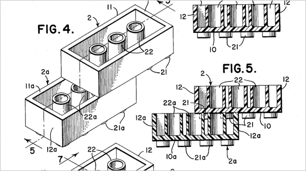
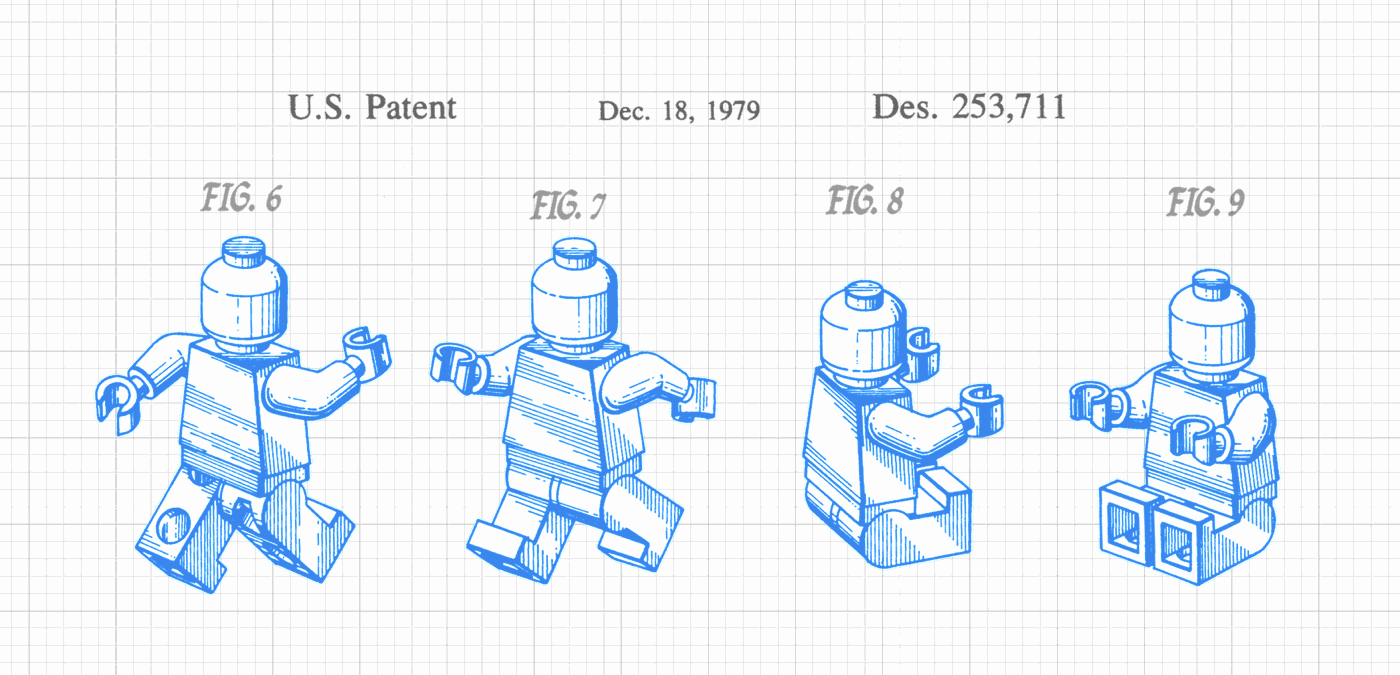
Arguably one of the most enjoyable parts of a patent are the figures. These often have an old-timey feel to them due to their hand-drafted heritage, back in the days when blueprints were blue for a reason.
Ruler Rules
As in all things patentable a slew of rules comes to bear:
The drawings should include the features specified in the patent claims. The drawings can be anything such as an illustration of embodiments, chemical equations, stages, flow charts, reference numbers, several views, and photographs of the invention. The figures are usually in black 'ink' but the illustrations can be colored if you can argue there is a need for such. The margins should be
- top: 2.5 cm
- left side: 2.5 cm
- right side: 1.5 cm
- bottom: 1.0 cm.
and the pages in the figures section are usually numbered in a A/B format (like 11/13 where the current page number is 11 out of 13).
Some further detail for those pagination sticklers amongst us:
7 CFR 1.165 Plant drawings
(a) Plant patent drawings should be artistically and competently executed and must comply with the requirements of § 1.84. View numbers and reference characters need not be employed unless required by the examiner. The drawing must disclose all the distinctive characteristics of the plant capable of visual representation.
(b) The drawings may be in color. The drawing must be in color if color is a distinguishing characteristic of the new variety. Two copies of color drawings or photographs must be submitted.
37 CFR 1.84 Standards for drawings.
(f) Size of paper. All drawing sheets in an application must be the same size. One of the shorter sides of the sheet is regarded as its top. The size of the sheets on which drawings are made must be:
(1) 21.0 cm. by 29.7 cm. (DIN size A4), or
(2) 21.6 cm. by 27.9 cm. (8 1/2 by 11 inches).
(g) Margins. The sheets must not contain frames around the sight (i.e., the usable surface), but should have scan target points (i.e., cross-hairs) printed on two cater-corner margin corners. Each sheet must include a top margin of at least 2.5 cm. (1 inch), a left side margin of at least 2.5 cm. (1 inch), a right side margin of at least 1.5 cm.(5/8 inch), and a bottom margin of at least 1.0 cm. (3/8 inch), thereby leaving a sight no greater than 17.0 cm. by 26.2 cm. on 21.0 cm. by 29.7 cm. (DIN size A4) drawing sheets, and a sight no greater than 17.6 cm. by 24.4 cm. (6 15/16 by 9 5/8 inches) on 21.6 cm. by 27.9 cm. (8 1/2 by 11 inch) drawing sheets.
(i) Arrangement of views. One view must not be placed upon another or within the outline of another. All views on the same sheet should stand in the same direction and, if possible, stand so that they can be read with the sheet held in an upright position. If views wider than the width of the sheet are necessary for the clearest illustration of the invention, the sheet may be turned on its side so that the top of the sheet, with the appropriate top margin to be used as the heading space, is on the right-hand side. Words must appear in a horizontal, left-to-right fashion when the page is either upright or turned so that the top becomes the right side, except for graphs utilizing standard scientific convention to denote the axis of abscissas (of X) and the axis of ordinates (of Y).
(t) Numbering of sheets of drawings. The sheets of drawings should be numbered in consecutive Arabic numerals, starting with 1, within the sight as defined in paragraph (g) of this section. These numbers, if present, must be placed in the middle of the top of the sheet, but not in the margin. The numbers can be placed on the right-hand side if the drawing extends too close to the middle of the top edge of the usable surface. The drawing sheet numbering must be clear and larger than the numbers used as reference characters to avoid confusion. The number of each sheet should be shown by two Arabic numerals placed on either side of an oblique line, with the first being the sheet number and the second being the total number of sheets of drawings, with no other marking.
(u) Numbering of views.
(1) The different views must be numbered in consecutive Arabic numerals, starting with 1, independent of the numbering of the sheets and, if possible, in the order in which they appear on the drawing sheet(s). Partial views intended to form one complete view, on one or several sheets, must be identified by the same number followed by a capital letter. View numbers must be preceded by the abbreviation “FIG.” Where only a single view is used in an application to illustrate the claimed invention, it must not be numbered and the abbreviation “FIG.” must not appear.
(2) Numbers and letters identifying the views must be simple and clear and must not be used in association with brackets, circles, or inverted commas. The view numbers must be larger than the numbers used for reference characters.
(x) Holes. No holes should be made by applicant in the drawing sheets
7.1 Flow Sheets and Diagrams
Flow sheets and diagrams are considered drawings.
PCT Rule 11
Physical Requirements of the International Application Size of Sheets The size of the sheets shall be A4 (29.7 cm x 21 cm). However, any receiving Office may accept international applications on sheets of other sizes provided that the record copy, as transmitted to the International Bureau, and, if the competent International Searching Authority so desires, the search copy, shall be of A4 size. Words in Drawings (a) The drawings shall not contain text matter, except a single word or words, when absolutely indispensable, such as “water,” “steam,” “open,” “closed,” “section on AB,” and, in the case of electric circuits and block schematic or flow sheet diagrams, a few short catchwords indispensable for understanding. (b) Any words used shall be so placed that, if translated, they may be pasted over without interfering with any lines of the drawings.
Special Requirements for Drawings
(a) Drawings shall be executed in durable, black, sufficiently dense and dark, uniformly thick and well-defined, lines and strokes without colorings.
(b) Cross-sections shall be indicated by oblique hatching which should not impede the clear reading of the reference signs and leading lines.
(c) The scale of the drawings and the distinctness of their graphical execution shall be such that a photographic reproduction with a linear reduction in size to two-thirds would enable all details to be distinguished without difficulty.
(d) When, in exceptional cases, the scale is given on a drawing, it shall be represented graphically.
(e) All numbers, letters and reference lines, appearing on the drawings, shall be simple and clear. Brackets, circles or inverted commas shall not be used in association with numbers and letters.
(f) All lines in the drawings shall, ordinarily, be drawn with the aid of drafting instruments.
(g) Each element of each figure shall be in proper proportion to each of the other elements in the figure, except where the use of a different proportion is indispensable for the clarity of the figure.
(h) The height of the numbers and letters shall not be less than 0.32 cm. For the lettering of drawings, the Latin and, where customary, the Greek alphabets shall be used.
(i) The same sheet of drawings may contain several figures. Where figures on two or more sheets form in effect a single complete figure, the figures on the several sheets shall be so arranged that the complete figure can be assembled without concealing any part of any of the figures appearing on the various sheets.
(j) The different figures shall be arranged on a sheet or sheets without wasting space, preferably in an upright position, clearly separated from one another. Where the figures are not arranged in an upright position, they shall be presented sideways with the top of the figures at the left side of the sheet.
(k) The different figures shall be numbered in Arabic numerals consecutively and independently of the numbering of the sheets.
(l) Reference signs not mentioned in the description shall not appear in the drawings, and vice versa.
(m) The same features, when denoted by reference signs, shall, throughout the international application, be denoted by the same signs.
(n) If the drawings contain a large number of reference signs, it is strongly recommended to attach a separate sheet listing all reference signs and the features denoted by them.
Some PCT miscellania
Drawings may not be included in the description, the claims or the abstract.
All lines in the drawings must, ordinarily, be drawn with the aid of a drafting instrument and must be executed in black, uniformly thick and well-defined lines. Color drawings are not acceptable.
All of the figures constituting the drawings must be grouped together on a sheet or sheets without waste of space, preferably in an upright position and clearly separated from each other. Where the drawings cannot be presented satisfactorily in an upright position, they may be placed sideways, with the tops of the drawings on the left-hand side of the sheet.
The usable surface of sheets (which must be of A4 size) must not exceed 26.2 cm x 17.0 cm. The sheets must not contain frames around the usable surface.
All sheets of drawings must be numbered in the center of either the top or the bottom of each sheet but not in the margin in numbers larger than those used as reference signs in order to avoid confusion with the latter. For drawings, a separate series of page numbers is to be used. The number of each sheet of the drawings must consist of two Arabic numerals separated by an oblique stroke, the first being the sheet number and the second being the total number of sheets of drawings. For example, “2/5” would be used for the second sheet of drawings where there are five in all.
Different figures on the sheets of drawings must be numbered in Arabic numerals consecutively and independently of the numbering of the sheets and, if possible, in the order in which they appear. This numbering should be preceded by the expression “Fig.”
In situations where one or more sheets are added, each sheet shall be identified by the number of the preceding sheet followed by a slant and then by another Arabic numeral such that the additional sheets are numbered consecutively, starting always with number one for the first sheet added after an unchanged sheet (e.g., 10/1, 15/1, 15/2, 15/3, etc.).
The PCT makes no provision for photographs. Nevertheless, they are allowed by the International Bureau where it is impossible to present in a drawing what is to be shown (for instance, crystalline structures). Where, exceptionally, photographs are submitted, they must be on sheets of A4 size, they must be black and white, and they must respect the minimum margins and admit of direct reproduction. Color photographs are not accepted.


Comments